Milling Machine with ISEL Microstep Card MPK-3
Introduction
Milling Machine with ISEL Microstep Card MPK-3 is a PC-controlled system developed using our technology of Windows Device Drivers for Low-Level Motion Control Boards.
Main application area is supposed as milling inscriptions and engravings.
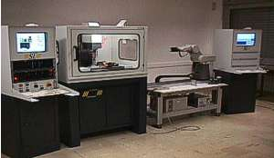
Figure 1: Milling Machine with ISEL Microstep Card MPK-3
Main Features
- High-speed and high resolution 3-axes coordinate motion system
- Single-table
- Vertical spindle
- Convenient tool change
- Adjustable workpiece positions
- Flexible trajectory control
- Windows standard imaging software support (CorelDraw, AutoCAD, etc)
- HPGL, CNC controlling
Component Parts
Hardware Components:
- IBM PC Compatible System with 2 ISA Slots
- ISEL Microstep Card MPK-3
- CS&IE Interrupt Generating Board
- ISEL 3-Axes Coordinate Table
Software Components:
- Microsoft Windows 2000
- Windows 2000 Hardware Driver
- Windows 2000 Port Monitor Driver
- Windows 2000 Printer Driver
- Windows 2000 Motion Control Configurator
ISEL Microstep Card MPK-3
ISEL Microstep Card MPK-3 is a product of ISEL Automation KG.
MPK-3 Card is a conscious attempt by ISEL to provide the customer with electronics, which can support - from the points of view of price, and of the open nature of the hard- and software architecture - a variety of applications.
The PC slot-in card contains all components necessary for driving 3 stepping motors, including 3 power end-stages. This card, especially when used in conjunction with ISEL stepping motors can meet the requirements of a variety of applications in the low- to medium power range.
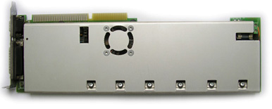
Figure 2: ISEL Microstep Card MPK-3
Technical Data
- 3-axis control card with integral power end-stages
- can be configured from full-step to micro-step
- long pc slot-in card (345 mm x 100 mm x 18 mm)
- fitted with cooling fan for optimum heat exchange
- logic voltage supply from PC
- bipolar stepping motor drive
- motor voltage +24V up to 36V max brought in from outside
- max operating current per motor 2A (chopped)
- over-temperature protection
- 3 optically isolated data switch inputs
- 3 free optically isolated inputs
- 1 relay output (24V / 1A)
- end stages can be switched off via software
- can be programmed to a higher programming language (interrupt controlled) if required
- setting base address by means of jumpers; installation of a number of cards is possible
- motor outputs, data switch inputs and motor voltage supply carried by a 25 pole sub-D connector
- in- and outputs carried by a 9-pole sub-D connector
Stepping Motors
Stepping motors are the important connecting link in technical operations in which input information is digitally processed and results in movement and positioning runs. They are capable, because of their operating principle, to act upon this digital information directly, without any further mechanical conversions. When a stepping motor is operated within a defined working range, feedback signals can be dispensed with. Because of its simplicity, the stepping motor is very frequently met with in practice.
Control Modes
Operating mode may be full- or half- or microstep, of which full- and half-step operation are the most commonly used.
This leads to the question - why then is it necessary to develop from full- and half-step to micro-step mode?
A weakness of full- and half-step operation appears at low speeds. Movement may be jerky. Also, because there is an obtrusive noise, it is unpleasant to be in the vicinity of such installations. This is of special significance in laboratories. The strong tendency towards resonating is a further reason for going over to micro-stepping.
Microstep Control
All ISEL stepping motors have a resolution of 200 steps per revolution. This figure can be manipulated by selecting electronically the way in which the motor windings are energized. The simplest variant is half-step mode with 400 steps per revolution. Due to the principle of control employed in the MPK-3 card, the motor can execute up to 25600 steps per revolution (i.e. 128 microsteps x 200 steps).
It is a major feature of the system that the motors are driven in the so-called microstep mode. The unpleasant noise and resonances normally associated with stepping motors are considerably reduced. Stepping motors are controlled with such a high resolution that your workpiece finish will be of exceptional quality.
Interrupt Generating Board
Our own Interrupt Generating Board was developed to support realtime control of the system under Windows 2000 operating system. It is based on three-channel one-chip programmable timer. Requirement of such a board is determined by the necessity of high-resolution timer with period of about 25 microseconds.
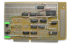
Figure 3: Interrupt Generating Board
Hardware Driver
Hardware Driver was developed to provide the possibility to work with various hardware systems that require control in realtime mode.
The Driver is fully configurable from application supplied with it. It is possible to enable or disable required axes, reverse axes, specify motion area, spindle pitch, velocity and acceleration for normal motion and initialization. There is a possibility for additional controlling parameters for various applications.
Motion control is implemented as trapezoidal shape of velocity on trajectory to provide customizable smooth motion. Hardware Driver can combine consecutive narrowly directed lines to be considered as a single trajectory reducing the number of acceleration and deceleration cycles. Angle of the maximum inclination between lines to be considered as "directed narrowly" can be specified as a parameter of the driver.
The Driver can accept input data in HPGL language, and it is capable to control various external tools (e.g. laser, mill, etc) concurrently with the motion.
Together with Printer Driver, it is possible to use Windows standard graphical applications (such as CorelDraw, AutoCAD, etc) to control 2- or 3-coordinate systems. Having the 3rd coordinate as milling tool or laser, it is easy to engrave vector or raster graphics generated by graphical applications.
Printer Driver
Printer Driver is intended to take part in rendering process together with GDI. It produces data in HPGL format with certain extension to implement features of specific machines that have differences in structure and functionality from usual plotters but are still closer to them than to any other computer peripherals.
Printer Driver is implemented like Windows Plotter Driver. It also has a set of pen options and a set of specific options for a machine.
Printer Driver works with vector and raster data. It distinguishes different colors reflecting them to tool parameters. For milling machine, user can specify motion speed and acceleration during drawing with configured pen as well as the spindle rotation speed corresponding to "pen down" state for every pen. User is prompted to set the type and size of drawing area.
Port Monitor Driver
Port Monitor Driver consists of user-mode DLLs. It is responsible for providing a communication path between user-mode print spooler and kernel-mode port drivers that access I/O port hardware. It is also responsible for management and configuration of server printer ports.
Structure
Port Monitor consists of two DLLs:
Port Monitor User Interface DLL:
Port Monitor UI DLL contains user interface functionality and executes on print client systems. This DLL must reside in the client system System32 sub-directory.
Port Monitor Server DLL:
Port Monitor Server DLL contains port communication functionality and executes on print servers. It must not display a user interface.
Main Features
- Decoding of HPGL or CNC commands produced by standard or specialized software (e.g. CorelDraw, AutoCAD, etc) and translating them into basic commands of Hardware Driver.
- Distributed and local control of the milling process.
- Setup and control over all parameters of Hardware Driver.
- Support of remote milling process over LAN or Internet, allowing a single milling machine being shared and controlled from several terminals.
User Interface
Screenshots of Port Monitor User Interface are shown in Figures 4-7.
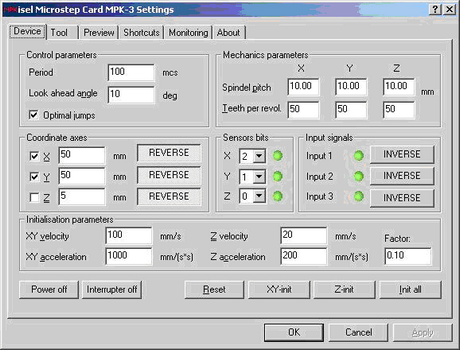
Figure 4: Port Monitor Driver - Device Settings
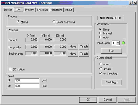
Figure 5: Port Monitor Driver - Tool Settings
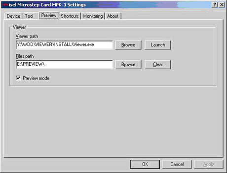
Figure 6: Port Monitor Driver - Preview Settings
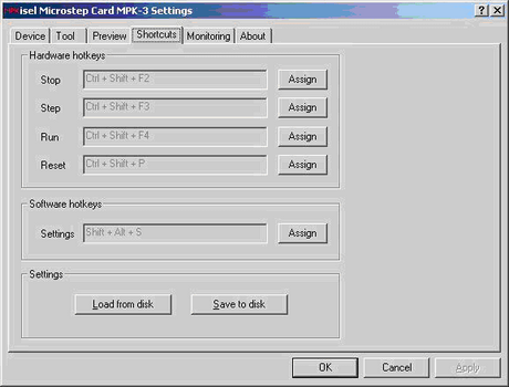
Figure 7: Port Monitor Driver - Shortcuts Settings
Motion Control Configurator
Motion Control Configurator is a Windows tray application intended for easy one-click control of printing process. It provides a good alternative to standard Windows “Printer Settings” dialog.
Screenshots of Motion Control Configurator are shown in Figures 8-9.
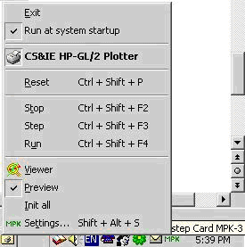
Figure 8: Motion Control Configurator - Application Menu
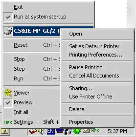
Figure 9: Printer Driver Menu
Conclusion
Milling Machine with ISEL Microstep Card MPK-3 controls up to 3 stepping motors with extremely high resolution and accuracy. Hardware and software set provides a very flexible and precise realtime control for a variety of applications in the low- to medium power range. Hardware Driver is configurable by the means of Motion Control Configurator. Together with Printer Driver, it is possible to use Windows standard graphical applications (such as Corel Draw, AutoCAD, etc) to control 2- and 3-coordinate systems. In combination with Printer and Port Monitor Drivers, the whole system is very flexible and convenient to use.